Stepper Motor Controller
This stepper motor controller is base on my previous example related to Injection System Behavior. As You can see from related YouTube video, stepper motor behavior could be easily changed by injection into the generic state machine. Injection is done over RS232 and USART terminal.
Version: 1.0.0.0
Provided material for download contains several bin files related to stepper motor behavior.
ContinuousRotateLeft.bin - transition matrix - stepper behavior #1
ContinuousRotateLeftAngle.bin - transition matrix - stepper behavior #2
ContinuousRotateRight.bin - transition matrix - stepper behavior #3
StepByStepRotateLeft.bin - transition matrix - stepper behavior #4
StepByStepRotateRight.bin - transition matrix - stepper behavior #5
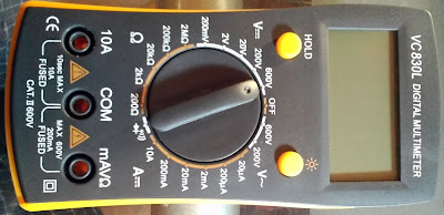
Electronics: beside priority encoder for external commands encoding,
interface between 8051 MCU and stepper motor is done over device driver
BA12004 IC (replacement: ULN2xxx series - motor driver kit).
As You can see from state diagrams, stepper motor is modeled as state machine. It is important to define all stepper motor states in order to achieve desired behaviors.
 | |
| Stepper motor state machine #1 |
 |
| Stepper motor state machine #2 |
Version: 1.0.0.1
Stepper Motor - Speed Controller Changes: Additional state "SpeedState" is added in order to achieve motor speed regulation. Interrupt handler routines are removed from state machine - timers and external interrupts will be handled by "default state method" as all other external commands encoded by priority encoder. Direct and indirect transition flags are optimized - instead of two BYTE fields only one BYTE field is used to indicate state flags. Currently only two MSB are used in order to provide state flags. Transition matrix is 50 bytes long - first byte for start state and 49 for system behavior. Currently transition matrix takes a lot of unused memory (0xFF fields) and it will be modified soon by adding transition matrix mode. Each transition matrix mode will present number of bits for state encoding.
Notes: Provided material for download includes
ContinuousRotation-SpeedController.bin file as speed controller example.
By appending seven additional bytes at the end of the file, bin files
from previous version could be easily expanded to 50 bytes.
Version: 1.0.0.2
Main changes are made on transition matrix, by adding state encoding
mode. Currently there are two encoding modes called xModes: x1Mode:
default mode, one BYTE per state allows 255 different kind of states
(too large transition matrix structure for small memory models) x2Mode:
it is used by version 1.0.0.2, one BYTE per two state allows 15
different kind of states (requires less amount of space than x1Mode).
Suitable for state machines with <= 15 states. DT, PS and CMD
transitions are no longer fixed. State flag is used to set transition
priorities. State machine engine is also changed regarding transition
matrix changes.
For more details look at : TransitionMatrix.h,
TransitionMatrix.c, StateMachine.h and StateMachine.c


Comments
Post a Comment