Feel the force around you – Frictional force Part V
This
is the fifth article related to the frictional force in order to
explain how to calculate required DC motor torque, first necessary step before
we proceed with a DC
motor selection from real manufacturer catalogs.
Normal force - Real catalog examples and calculations
Feel the force around you – Frictional force Part I
Feel the force around you – Frictional force Part II
Feel the force around you – Frictional force Part III
Feel the force around you – Frictional force Part IV
Programmable autonomous vehicles – Fundamentals, Part I
To proceed with torque calculations, we will be concentrate
around figure number 1, which presents wheel on the incline surface with angle
theta. Incline calculations are general, because they
cover zero angle scenario. The wheel has weight as any other
object and it is a force, with composite nature. First component of the force push
object to the ground, generating at the same time normal force in the opposite equilibrium
direction (cosine part of the weight force).
 |
| Figure 1. Wheel on the incline, with angle theta. |
Second
force is pulling force, sinus part of the weight force, with tendencies to roll
wheel down the incline. Sinus part of the weight force works against wheel
rolling in the upward incline direction. To roll wheel in upward incline direction, DC
motor must provide enough torque to overcome sinus part of the weight force (do not forget
that weight force is not just a weight of the wheel, it is a complete mobile robot weight)
 |
| DC Motor torque calculations |
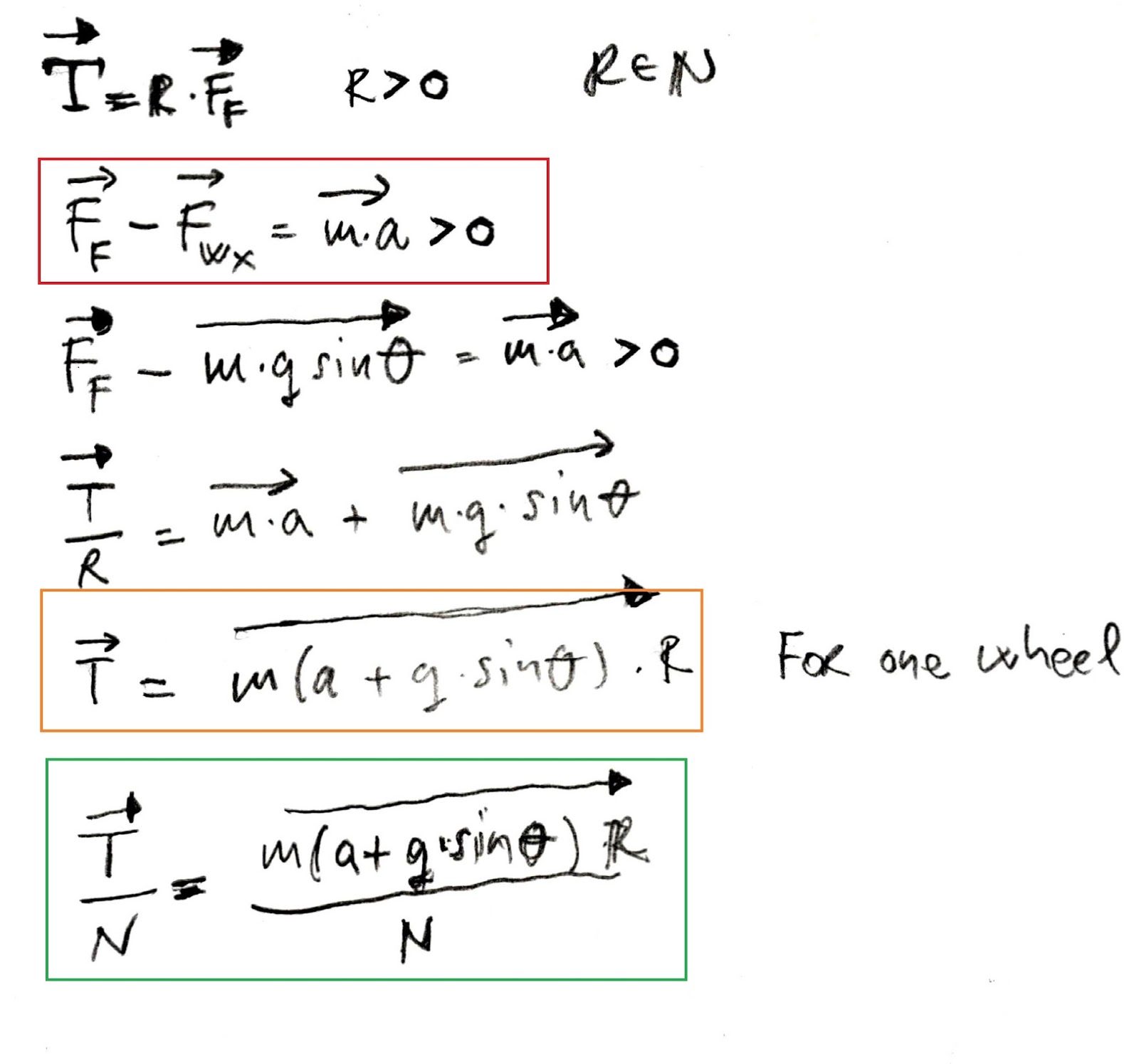
No friction, no
motion, it is a simple rule. Frictional force Ff provides motion in the upward incline direction,
and it is defined as Ff = T/R, where T is torque (the momentum of the force) generated
by a DC motor
and R is wheel radius. Second, cosine part of the weight force is not
interesting to us, and it is excluded from the calculations, because, it does
not affect motion in any direction – it is a down force which generates
normal force in an
opposite equilibrium direction.
First
equation, rounded with red rectangle is the key point equation, a starting
point. The equation
says, that frictional force Ff must be greater than a sinus part of the weight force
(Fwx) in order for the mobile robot to proceed with the motion in upward incline
direction, and it is generated by a DC motor. In the reverse scenario,
when frictional force is less than sinus part of the weight, mobile robot will
be pulled down to the ground surface.
Once we do all the replacements in the first equation, final equation rounded with an orange rectangle, is DC motor torque equation and it is related only to one wheel. If a mobile robot contains more than one wheel, for example, two wheels, in that case, torque equation is divided by two. In general, the DC motor torque equation is divided by N, where N stands for the number of wheels and it could be 1,2,3,4… That also means that required DC motor torque is equally split to all mobile robot driven wheels (do not forget that some mobile robot types like differential robot, has a third wheel with purpose to stabilize mobile robot mass balance, but it is not driven by the DC motor driver like it is SERPENT I or ULN2803, or any other type of DC motor driver/controller, Figure 2.).
Once we do all the replacements in the first equation, final equation rounded with an orange rectangle, is DC motor torque equation and it is related only to one wheel. If a mobile robot contains more than one wheel, for example, two wheels, in that case, torque equation is divided by two. In general, the DC motor torque equation is divided by N, where N stands for the number of wheels and it could be 1,2,3,4… That also means that required DC motor torque is equally split to all mobile robot driven wheels (do not forget that some mobile robot types like differential robot, has a third wheel with purpose to stabilize mobile robot mass balance, but it is not driven by the DC motor driver like it is SERPENT I or ULN2803, or any other type of DC motor driver/controller, Figure 2.).
 |
| Figure 2. Differential mobile robot with two driven wheels and one mass balance wheel. |
Before we start with DC motor torque calculations, it is
important to determine the maximum incline angle (theta),
because it is directly reflected to required DC motor torque (as we can see
from the provided
equation), but not just that, it also reflects final costs of the
chosen DC motors. Higher incline angle, more required torque (and vice versa),
leads in two directions:
to buy more powerful DC motor with ability to generate required
torque, or to buy less power DC motor with gearbox reductor. Pay attention here that number of
wheels reduces required torque per DC motor (as we can see from provided
equations). Which of these two scenarios is better, it is hard to say, but that
is the next step after torque calculations are completed. Let’s go back to
angle theta.
To determine angle theta, we should know precisely terrain
configuration – mobile robot environment. If the terrain configuration does not include
inclines, that means that angle theta is zero, and DC motor torque calculation
includes the complete
weight of the mobile robot. If terrain includes inclines, maximum
incline should be used in DC motor torque calculations. For example: if the terrain
has three inclines: 20, 30 and 65 degrees, in that case, 65 degrees is maximum incline,
and it should be used to determine required DC motor torque. If 30 degrees
angle is used in provided torque calculations, in that case, mobile robot has the ability
to overcome 20 and 30 degrees inclines, but it will be stuck on 65 degrees
inclines, without possibility to overcome sinus part of his own weight force.
Pay attention here that provided torque calculations does
not include
any kind of information about frictional force coefficients, type of wheel
surface and ground surface. In general, there are no details about the materials
used to build a wheel,
for example. Calculations are used only to determine required DC motor torque
against total mobile robot weight and inclines. That means, for example, that
mobile robot will perfectly work for a tire and wood surface materials
combination, and have a lot of problems with wheels spinning on the ice ground surface.
This kind of problems could be resolved by playing with different material
types regarding wheels and ground surfaces.
Generally speaking, the mobile robot development includes several different steps which should be completed in exact order to avoid any kind of potential problems.What does that mean? That means that it is not possible to design DC motor driver/controller (DC motor current consumption plays important part regarding DC motor driver/controller design) if we do not know required DC motor torque or even which DC motor will be selected as right one. First, it is important to determine/calculate required DC motor torque, than to select appropriate DC motor and than to design/choose/buy DC motor driver/controller. Otherwise we will have a lot of issues in order to achieve requested mobile robot requirements.
Related articles:
Feel the force around you – Normal forceNormal force - Real catalog examples and calculations
Feel the force around you – Frictional force Part I
Feel the force around you – Frictional force Part II
Feel the force around you – Frictional force Part III
Feel the force around you – Frictional force Part IV
Programmable autonomous vehicles – Fundamentals, Part I


Dc gear motor 25mm diameter
ReplyDeleteJGA25-370 25mm Gear Box 1360 620 280 170 130 77 60 35 26 16 12 RPM 12v Electric High Torque 9kg.cm 6v 24v brush Dc Geared Motor for Home Appliance
Model: JGA25-370
To Buy Click Here: Dc gear motor 25mm diameter