DC motor torque vs DC motor speed
This
blog post article is intended to show you the relation between DC motor torque
and DC motor speed for the provided PWM signal and frequency. It is covered by
three different video clips for three different PWM modulation signals. This is
initial version of the blog post and it will be changed in time. In the near
future more video clips will be presented with different types of motors in
order to show you how DC motor torque and speed depends on each other regarding
provided PWM modulation including DC motor current consumption.
Pulse Width Modulation (in short: PWM) is control method with possibility to apply different voltage levels to the DC motor wire coils. Here we are dealing with DC motors with only two wires controlled in these examples by SERPENT I DC motor controller and VF driver (variable frequency driver - new zilsel-invent product). VF driver PCB is built as a prototype version with the thermal transfer method. It is not intended for professional PCB manufacturing since it is a revision number one and documentation is available for free. Anyway, VF driver is an adjustable variable frequency driver with possibility to find the right frequency for DC motor including PWM modulation capabilities.
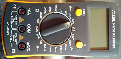
VF Driver frequency measurements with digital multimeter. This video clip is intended to show frequency measurement related to the VF driver with a digital multimeter. 20KHz is maximum measurement limitation. 11KHz is starting generated frequency, by placing a jumper at 104 ceramic multilayer capacitors, the total capacitance of the VF driver is increased, so that is the reason why frequency is decreased to above 6KHz. When a jumper is removed, frequency goes back to the 11KHz. Set of four different capacitance, in this case, two 104 ceramic multilayer and two 2n2 disk ceramic capacitors are responsible for frequency generation including POT configured to work as a variable resistor. By changing resistance and total capacitance, VF driver generates different frequencies. As you can see from the video clip, generated frequency is stable. More capacitance and greater resistance generate lower frequencies and vice versa.
As you will see from provided videos, it is possible to control DC motor with low level impulses which brings threshold voltage Vth to the DC motor wires just to start the slowest possible rotation. In provided figure #1, diagram presents the relation between a DC motor torque and DC motor speed for complete set of different PWM duty cycles starting from the slowest rotation related to Vth and ending to the highest speed defined by 100% PWM duty cycle. By changing PWM signal, we are actually changing position of the DC motor torque vs speed curve (bold dotted line) and position changes are done in parallel between minimum curve and maximum curve as it is shown in the diagram. What does that mean? It means that it is not possible to change DC motor speed and not to change DC motor torque for providing PWM duty cycle. By PWM duty cycle changes the torque and the speed are changed accordingly, both at the same time, which is the reason why we noted that changes are made in parallel between minimum and maximum DC motor vs speed curve.
 |
| VF Driver Rev#1 - prototype version |
VF Driver frequency measurements with digital multimeter. This video clip is intended to show frequency measurement related to the VF driver with a digital multimeter. 20KHz is maximum measurement limitation. 11KHz is starting generated frequency, by placing a jumper at 104 ceramic multilayer capacitors, the total capacitance of the VF driver is increased, so that is the reason why frequency is decreased to above 6KHz. When a jumper is removed, frequency goes back to the 11KHz. Set of four different capacitance, in this case, two 104 ceramic multilayer and two 2n2 disk ceramic capacitors are responsible for frequency generation including POT configured to work as a variable resistor. By changing resistance and total capacitance, VF driver generates different frequencies. As you can see from the video clip, generated frequency is stable. More capacitance and greater resistance generate lower frequencies and vice versa.
As you will see from provided videos, it is possible to control DC motor with low level impulses which brings threshold voltage Vth to the DC motor wires just to start the slowest possible rotation. In provided figure #1, diagram presents the relation between a DC motor torque and DC motor speed for complete set of different PWM duty cycles starting from the slowest rotation related to Vth and ending to the highest speed defined by 100% PWM duty cycle. By changing PWM signal, we are actually changing position of the DC motor torque vs speed curve (bold dotted line) and position changes are done in parallel between minimum curve and maximum curve as it is shown in the diagram. What does that mean? It means that it is not possible to change DC motor speed and not to change DC motor torque for providing PWM duty cycle. By PWM duty cycle changes the torque and the speed are changed accordingly, both at the same time, which is the reason why we noted that changes are made in parallel between minimum and maximum DC motor vs speed curve.
 |
| Figure #1: DC motor torque vs DC motor speed |
Video
#1 - Threshold voltage (Vth) and slowest possible speed
This
first video is a demonstration about the relationship between DC motor torque
and speed for the threshold voltage Vth generated by VF driver. We already
noted that it is not possible to change DC motor speed without torque changes,
both values are changed at the same time. Rotation of the DC motor shaft is too
slow, a very small applied load is good enough to stop DC motor shaft rotation
since DC motor torque is too small in this case. As you can see, with naked
fingers it is possible to stop DC motor shaft rotation very easily. We have to
pay attention here, without load, DC motor torque does not exist, and it is a
zero. When load is applied to the DC motor shaft, DC motor torque start to
react in the opposite direction with tendencies to continue with shaft
rotation. The load is external applied force, it could be a finger like in this
example, or it could be some mechanical part like wheel, for example, but
anyway external load to the DC motor shaft has tendencies to stop DC motor
shaft rotation, while DC motor torque works in the opposite direction.
Another,
very important parameter is current consumption related to different PWM duty
cycles. In this case as digital multimeter has been measured, about 0.01
amperes is current consumption regarding PWM duty cycle and threshold voltage (Vth),
even in case when external load is applied to the DC motor shaft. That is very
small current consumption with very small power losses, but provided DC motor
speed as well as torque are useless since it is not possible to drive anything
heavy.
Video
#2 - DC motor torque vs speed and current consumption
Video
#2 is related to higher speed in comparison to the video #1. The PWM duty cycle
is above DC motor voltage threshold and it rotates with higher speed – RPM rotation
per minute. As we can see from the provided video the current consumption
regarding free running mode (without externally applied load) is a little bit
more in comparison with the first video example, it is 0.02 amperes. Now, pay attention
to the current consumption in case when external load is applied to the DC
motor shaft. In some cases, digital multimeter has been measured around 0.07
amperes. It is not too much current, but there is a certain difference in
comparison with video #1, the current consumption is higher and it has been
increased when external load has been applied to the motor shaft. Now we will
increase PWM duty cycle up to 100% and see what’s happening, so pay attention
on the third video clip.
Video
#3 - DC motor torque vs speed and current consumption
Video
#3 is related to the maximum voltage applied across the DC motor wire coils
since the PWM duty cycle is set to 100% presently. Since, RPM rotation per
minute has a maximum value, protect your naked fingers with insulation tape
since friction between the fingers and the motor shaft is too high and you will
feel the heat, so do not do that without naked fingers. It is very hard to stop
DC motor shaft rotation in this case since RPM has maximum value, including DC
motor torque, which acts in the opposite direction immediately when you touch
motor shaft with fingers. The RPM is maximum and we can see more clearly how DC
motor consumes much more current when it is loaded with externally applied
force (load). In some cases DC motor shaft rotation is stopped completely and
digital multimeter has been measured above 0.5 amperes, in some cases it was
above 0.6 amperes. If external load is increasingly applied to the shaft, current consumption
increases as well, and it reaches a maximum in case when motor shaft is
completely stopped. When the DC motor shaft is completely stopped while it is
in running mode, it is called a stall mode. The DC motor stall mode is not very
well welcomed, since the DC motor could be damaged permanently with high DC
currents, including DC motor controller/driver.
YES, it is very bad when your DC motor stall in
free running mode, higher current flows through DC motor, since there are no
back electromotive force which works against applied electrical power, more
worse, it gets heated which led to overheat since DC motor has ESR or
equivalent serial resistance. But that is not all, DC motor driver starts to
heat, which lead to overheating, in a worst case scenario, DC motor
driver/controller could be melted with very high DC current, so heatsinks and
thermal cooling plays important part in the DC motor design. Yes, it is very
bad when the DC motor stalls in running mode, no rotation at all, and high
current flows through DC motor coils as well as DC motor controller. But
anyway, there are protections against a DC motor stall, where you actually
measure current consumption with shunt resistor and switch off complete
electronics (H-Bridge) when current consumption becomes critical, with simple
reason to avoid any kind of damage etc.
Video #4 - DC motor torque vs speed and current consumption
In this example different DC motor is used, the specification is not available, but it is more powerful DC motor in comparison with DC motor regarding first three videos. Anyway: by increasing the applied external load, DC current consumption also increases, and vice versa. In this case at DC motor stall, current consumption is over 1 amperes, much more in comparison to the first three examples.
Conclusion
Let’s make conclusions with these four video
examples. First, DC motor current consumption is small when DC motor is running
without externally applied force – free running mode. Current consumption
increases when external load is applied to the DC motor shaft. If the DC motor
shaft is stalled, with too high externally applied load, not able to be overcome with DC
motor torque, the highest current flows through DC motor coils and DC motor
controller as well, and permanent damage is not excluded. Heatsink design plays an
important rule in DC motor controller/driver design, including to choose right
power MOSFET able to handle maximum rated DC motor current consumption. It is
not possible to change DC motor speed rotation without DC motor torque changes.
Both values are changed at the same time and values depends on the provided PWM
duty cycle generated by the VF driver.
In the near future, this blog post will be
updated with more features, videos, diagrams, etc. All changes under the blog
post will be shared under the social networking media.
zilsel-invent assumes no responsibility or liability for any errors or inaccuracies that may appear in the present document.
Specification and information contained in the present schematics are subject to change at any time without notice.
Related articles:
SERPENT I - DC motor controller
SERPENT I - PCB DIY (do it yourself) assembling - video clips examples
How to design LM324 Astable Multivibrator
How to build do it yourself printed circuit board (DIY PCB) by using thermal transfer method
Programmable autonomous vehicles – Fundamentals, Part I
Power switch as current amplifier
How to design voltage reference by limiting current consumption
Fake VC830L digital multimeter
zilsel-invent assumes no responsibility or liability for any errors or inaccuracies that may appear in the present document.
Specification and information contained in the present schematics are subject to change at any time without notice.


These technical details had been of great help. Thanks for sharing!!Keep updating new posts on your blog!!
ReplyDeletePower transformers in India | SMPS Transformer Manufacturer in India
Thank you for the comment! Best Regards!
DeleteThis is a really good post. Must admit that you are amongst the best bloggers I have read. Thanks for posting this.
ReplyDelete12v dc gear motor
Thank you for the comment! Best Regards!
Delete