Triangular oscillator - Fundamentals - I part
The Figure
#1 presents basic astable multivibrator circuit. This is the basis used for
many different applications like: capacitance measurement circuit used for the
digital multimeters (in some digital multimeters implementations), free running
square-wave signal generator, free running triangular signal generator and the variable
frequency drivers (VF Driver). In this case, this circuit is basis for the
variable frequency driver, used to drive the DC motor controllers with the pulse
width modulation (PWM) capabilities in order to provide DC motor torque and speed regulation.
General discussion
The
circuit (Figure #1) is consisted of the two main parts: the integrator and the
comparator with the hysteresis. The comparator with the hysteresis is built around the operational
amplifier: OpAmp (2), resistor R2, resistor R3 and the reference voltage defined by the position of
the potentiometer P1. The resistor R3 is the feedback resistor and it
is used to feedback current state of the output voltage (at pin 7 – OpAmp (2), this is
square-wave signal which means that ~Vcc or ~0 volts are possible values)
back to the non-inverting high impedance input (pin 5 – OpAmp (2)), in order to
provide two different threshold voltages: Vth (voltage threshold high) and Vtl
(voltage threshold low). These two reference voltages are used to switch
capacitor C1 between charging and discharging states, at the same time
generating the triangular signal at point marked with (1) – See also Figure #2.
 |
| Figure #1: Triangular / Square-wave generator circuit. |
The
integrator circuit is built around the resistor R1, the operational amplifier
OpAmp (1), the capacitor C1 and the reference voltage defined by the position of
the potentiometer P1. Together, the integrator and the comparator
with hysteresis built astable multivibrator, and it is a free running
multivibrator. Switching frequency depends on the resistance values and
capacitance as well, but you will see in the upcoming articles that there are
different configurations in order to change the frequency in running mode: by
changing the capacitance (C1) with variable capacitor or by multiple capacitors in parallel, or by changing the R2 value with the variable resistor (at the same time to change
the hysteresis triggering configuration) etc.
 |
| Figure #2: Triangular signal and hysteresis threshold voltages: Vth and Vtl |
The switching frequency regarding the first revision of the VF driver (project link is here) is based on the capacitance changes consisted of the multiple capacitors in the parallel and by changing the resistor R2 value with different set of potentiometers configured as the variable resistors. By changing R2 with variable resistor, hysteresis is automatically adjusted at the same time providing different voltage triggering points (two different reference voltages: Vth and Vtl). Changing capacitance, by using jumpers to add or remove extra capacitance value to the total capacitance of the integrator, charging and discharging time are changed accordingly. Greater the total capacitance means lower the frequency and vice versa (smaller the total capacitance means higher the frequency). But one should be clear, the frequency is one thing, and frequency does not have nothing with the signal shape (how signal looks like). Signal can be anything, and if it is periodically changed in time, that means that it has frequency (number of period oscillations per second). In case of the variable frequency driver (VF driver) it is important for the generated signal to be square-waved (Figure #3), and that means that slew-rate of the operation amplifier plays important rule. We already have had discussions about slew-rate (How to design LM324 Astable Multivibrator) and we will see in the upcoming articles how to do calculation in order to choose the adequate operational amplifier able to generate desired square-wave signal with desired frequency.
 |
| Figure #3: Square-wave signal, point marked with number (2) at Figure #1 |
Circuit
from the Figure #1 is not complete, there are a lot of missing different components around
this basic schematic necessary to build the variable frequency driver, and it
will be presented in the upcoming articles. For example, driving output of the VF
driver must be buffered (amplified) if chosen operational amplifier does not
have appropriate current source output requirement, etc. So there are a lot of missing
components from this basic schematic presented on the Figure #1, but it is
fundamental circuit, necessary to build: signal generators (triangular or
square-wave), variable frequency driver or measurement circuit with
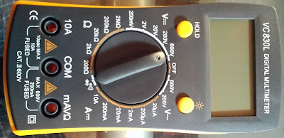
capabilities to do capacitance measurement. Yes, in some implementation of digital multimeters (Figure #4) this circuit is used for capacitance
measurements.
 |
| Figure #4: Capacitance measurement |
By placing the capacitor at connectors dedicated to the capacitor
measurement, capacitor is actually placed at the point where the capacitor C1 is
presented on the Figure #1. Different values of the capacitors means different
generated frequency. Generated square-wave signal goes directly to the counter
(part of the microcontroller) which counts number of square-wave signal
oscillations per second. Number of counts defines frequency, and if we do know frequency,
that means that central processing unit of the digital multimeter is capable to
do calculations and determines capacitance of the capacitor connected to
digital multimeter, simple ;-).
Related video: PCB prototype Adjustable Variable Frequency Driver. Triangular signal taken with oscilloscope. SERPENT II DC motor driver is used for this video presentation.
Related video: PCB prototype Adjustable Variable Frequency Driver. Square-wave signal taken with oscilloscope. SERPENT II DC motor driver is used for this video presentation.
Related articles:
Triangular oscillator - Frequency - II part
Triangular oscillator - PWM square wave signal - III part
Triangluar oscillator - Operational amplifier slew rate - IV part
SERPENT I - DC motor controller
SERPENT I - PCB DIY (do it yourself) assembling - video clips examples
SERPENT II - Pit VIPER Rattle - DC motor controller/driver
How to design LM324 Astable Multivibrator
How to build do it yourself printed circuit board (DIY PCB) by using thermal transfer method
Programmable autonomous vehicles – Fundamentals, Part I
Power switch as current amplifier
How to design voltage reference by limiting current consumption
Fake VC830L digital multimeter
Low pass filter and voltage stabilization
zilsel-invent assumes no responsibility or liability for any errors or inaccuracies that may appear in the present document. Specification and information contained in the present schematics are subject to change at any time without notice.


Comments
Post a Comment