Programmable autonomous vehicles – Fundamentals, Part II
If we look inside ourselves and
think about what makes us autonomous beings, we can conclude that those are two
components: intelligence and senses. Everything we see, feel or hear, our
intelligence processes in terms of making conclusions/decisions. If we want to
give machines a point of view it’s clear that we have to equip them with senses
– sensors – electro/mechanical devices that allow a certain level of autonomic
behavior. The choice and practical realization of the sensors is the next step
after choosing a motor, device driver and microcontroller, about which you had
a chance to read in the first part about programmable autonomic vehicles.
Types and sensor selection
Like DC motors, sensors selection
depends on the tasks that programmable autonomous vehicle completes. So we
have: sensors for detecting objects in space (Infrared and Mechanical Sensors),
sensors for measuring temperature/humidity of the room (Temperature and
Humidity Sensors), sensors for DC motors (Encoders and Disk Sensors – Feedback Motor Control Systems)
etc. If you want to bypass practical realization of the sensors, you have a
wide selection of on-line stores with all the product details (http://www.robotshop.com/sensors.html).
Besides the crucial task of orientation in space, the other task is regulating
the speed of the driving DC motor, which will be discussed in this article.
 |
| Picture 1 - Mobile Robot Sensors |
Mechanical sensors
Mechanical sensors detect objects
by physical contact. They are used for realization of the orientation in space
task and are simple for practical realization. The Micro Switches (hereinafter
referred to as SW) used resemble insect tentacles. Picture 1c shows the
electrical schematic of the connection between SWs and microcontroller
(hereinafter referred to as MCU). At the moments of physical contact pull-up
resistors R1 and R2 are connected to the ground, whereby the pins P3.2 and P3.3
respectively generate a logic zero. Conversely, pins are set to logical units
(~+5V). Interrupt unit MCU is configured so that in time of decline from logic
unit 1 to logic unit 0 (falling triggering edge), there is a triggering of the
interrupt routine which guides the control unit to make a decision. The left
and right SW make the front set of the mechanical sensors. A separate PCB is
used in addition to the SWs also has tripolar screw connectors for coupling
sensor signals and interrupt unit. PCB is installed directly in front of the
front wheels (pictures 4 and 5). The back set of mechanical sensors is made of
one SW for detecting objects while moving the programmable autonomous vehicle
in reverse (picture 6).
 |
| Picture 4 - IR Sensor and front mechanical sensor |
Infrared sensors
Infrared (hereinafter referred to
as IR) sensor detects objects without physical contact. It is used for the task
of getting around in space. Sensor is built of two components: photo
transmitter and photo receiver which are installed side by side.
In the picture 1.a1. electrical scheme is shown for the IR sensors based on IR
LE diode (LD271 transmitter) and photo transistor (BPW77NB receiver). The
transmitter constantly emits an IR wave (950 nm) which is reflected back to the
receiver if there is an object in front of the receivers (picture 1.a2.), and
vice versa ( picture 1.a3.)
The intensity of the collector
current is inversely proportional to the distance between the photo transistors
and reflective surface of an object. As closer the vehicle gets to reflecting
surface, the collector current intensity rises, and vice versa. Therefore,
the difference in potential between the collector and emitter is an analog
signal that is unfit for direct connection with the MCU. And because of this
the connection between IR sensor and MCU is realized by implementing a
comparator – conversion of analog signal into digital – A/D convertor.
Comparator is made of operational amplifier (from hereinafter OpAmp) - LM324 IC circuit (picture 1d) . 2K potentiometer that is attached to the (-) input OpAmp defines reference voltage (for example +2.5V). Collector from the photo transistor is attached to the OpAmp’s (+) input. If the voltage on the (+) input is higher than the voltage on the (-) input, than the logic 1 is set on OpAmp’s output – conclusion, there isn’t an object in front of the vehicle. In the contrary, logic 0 is set on OpAmp’s output – conclusion, there is an object in front of the vehicle. In moments of transfer (on pin 1) from logic 1 to logic 0, the interrupt routine is triggered (EXT#0) which leads the controller unit to make a decision.
 |
| Picture 5 - IR Sensor and front mechanical sensor |
The diagram in picture 1.a4.
shows the conversion of the analog signal (1) into digital (2) compared to
reference voltage (3). To make things easier, analog signal is displayed as a
linear function of time. Note that by adjusting the reference voltage (3) we
are also adjusting the voltage threshold i.e. sensitivity (distance between an
object and the sensor) of the IR sensor. Additional configuring of sensitivity
is achieved with rheostats Rb and Rc (implemented FT-63 trimmer potentiometers,
102 and 105 retrospectively) by regulating the intensity of collector power of
the photo transistor. By increasing the resistance Rb, the sensitivity of the
IR sensor is decreased to stat light noises.
The IR sensor is implemented on a
separate PCB so it could use it for purposes of other projects. Finished PCB
with strip copper lines and drilled holes has been used. LM324 IC circuit (14
pins – picture 1d) is not directly soldered to the PCB, I used the DIP-18
socket that was at my disposal. IR LE diode and photo transistors are soldered next
to each other at the distance of 10 mm. The upper side of PCB is coated with
black isolating tape before the soldering to reduce / eliminate the unwanted
reflection of light (black surfaces don’t reflect light). Since IR light isn’t
visible to the human eye, the implemented sensor can be tested with CCD chip
i.e. with phone camera. Just point the camera to IR LE diode and you will see the
ray of IR light (you can try it with the remote controller). The IR sensor is
installed at the front side of the vehicle which completes the front set of
sensors (pictures 4 and 5).
 |
| Picture 2 |
Synchronization of the front
wheels and sensors
The front set of the sensor is
physically attached to the structure of the front wheels instead for the
supporting structure of a programmable autonomous vehicles, which is a
difference in comparison to a mechanical sensor on the rear (picture 6). A
configuration like that allows a simpler implementation of the managing
software. Let's see for example the situation in Picture 2. Suppose that the
programmable autonomous vehicle is currently moving forward and the IR sensor
has detected the object 1 (see picture 2a). At that point, we stop the vehicle
and rotate the front wheels to the left, thus rotating the front sensors during
which the IR sensor detects the object 2 (see picture 2b). Since the object 2
is an obstacle for the further movement, we change rotation to the right,
wherein the IR sensor detects the free space of a further movement (Picture
2.c). In the case of coupling of the front set of sensors with the support
structure of the programmable autonomous vehicle (picture 2.d), only the front
wheels are being rotated, whereby the IR sensor still detects the object
1! This is a complex situation for making a decision / conclusion, whether
there is an object in front of a programmable autonomous vehicles? If you want
to make your life easier, use the situations shown in Pictures 2a - 2c as
guide, and forget about Picture 2d.
 |
| Picture 8 - Rohm 547 sensor |
Feedback sensors for DC motors
Feedback sensor allows measuring
of the rpm of the DC motor in purpose of regulating it’s speed. In picture 1.b1. there is the electrical
schematics, based on Rohm 574 photo-interrupter sensor that makes a photo
transmitter (LE diode – 800nm wavelength) and photo receiver (photo
transistor). The working principle of Rohm 547 sensor is shown in pictures
1.b2. and 1.b3. If we put a bumper between the transmitter and the receiver,
the ray of light pointed to the receiver is interrupted by the bumper, thus the
photo receiver stops to lead (the cut-off area). Otherwise the photo transistor
leads (saturation area). If the bumper is installed on the shaft of DC motor,
the frequency speed defines the frequency that interrupts the ray of light. As
well as the IR sensors, the difference in potential between the collector and
the emitter of photo transistor is an analog signal which is converted to
digital using the comparator. As the interrupt unit MCU is set to trigger on
the decreasing edge of the signal, the collector of the photo transistor is
connected to (-) input on the OpAmp. The
inverted conversion of the analog signal (1) into digital (2) in relation to
the reference voltage level (3) is shown in picture 1.b4. Decreasing edge of
triggering (4) represents the moment in which the bumper intersects the ray of
light of the LE diode of the Rohm 547 sensor.
 |
| Picture 6 - Rear mechanical sensor |
Pulse-Width Modulation
The DC motor speed control is
done by regulating the voltage of the Vave (average voltage supply to DC motor) by using PW modulation
according to the following equation: Vave = ton
/ T * Vin.
Where: ton=
active time of Darlington’s transistors ULN 2803 circuit, T = period of PWM
signal, ton/T =
duty cycle (often expressed in %) and Vin = power source (12V). For example: if the ton = T, the duty cycle
is 1 (100%), that leads to Vave = Vin,
which contributes to the maximum speed of the DC motor. In case when ton
< T, for example by half, duty cycle is 0.5 (50%), which implies that the Vave= 6V during which
the engine speed decreases. The larger the duty cycle is, the speed of the
motor rises and vice versa. Active time, the period, the duty cycle and the PWM
frequency are determined by the software (MCU timers) according to Rohm 574
sensor’s collected signals (feedback). Before implementing the software pay
attention to the ton/toff time
specifications required by ULN 2803 IC circuits which must be fulfilled in order for the transistors to be
able to work stable (picture 3). If you want to bypass software implementation
of the PWM signal, you can implement it by using the LM324 circuit.
 |
| Picture 3 |
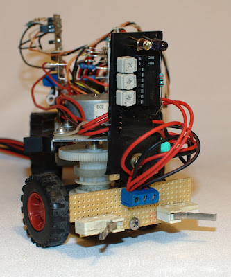
For sensor electronics of the DC
motor a separate PCB is used which is equipped with: LM324 circuit, trimmer
potentiometer (FT-63 series, 504) for defining the reference voltage of the
OpAmp and pin-head connectors used for easy assembly/replacement of the
components (picture 7). PCB is installed vertically on the supporting structure
of the autonomous programmable vehicle and parallel with ULN 2803 device
driver. The Rohm 574 sensor is installed on the bottom of the vehicle. On DC
motor’s drive shaft a bumper is installed for interrupting the ray of light
(picture 8). For stability, Rohm 574 sensor must be installed so that the bumper
engages the whole ray of light. The hardware part of the vehicle is completed
by practical implementation of the sensors. The final step is implementation of
the managing software which guides us into the domain of state machines with
final number of states and ‘infinite’ number of transitions between them, which
will be discussed more in the third part.
 |
| Picture 7 - Sensor electronics |
Author: Vladimir Savić
Related projects:
Related articles:
Feel the force around you – Normal forceNormal force - Real catalog examples and calculations
Feel the force around you – Frictional force Part I
Feel the force around you – Frictional force Part II
Feel the force around you – Frictional force Part III
Feel the force around you – Frictional force Part IV
Feel the force around you – Frictional force Part V
Power switch as current amplifier
SERPENT I - DC motor controller/driver
SERPENT I - PCB DIY (do it yourself) assembling - video clips examples
SERPENT II - Pit VIPER Rattle - DC motor controller/driver
How to build do it yourself printed circuit board (DIY PCB) by using thermal transfer method
DC motor torque vs DC motor speed
How to design voltage reference by limiting current consumption
Fake VC830L digital multimeter
zilsel-invent assumes no responsibility or liability for any errors or inaccuracies that may appear in the present document. Specification and information contained in the present schematics are subject to change at any time without notice.


Comments
Post a Comment